Blog / Neato D10 Brain Transplant / Ep. 18
episode 18
One wire at a time
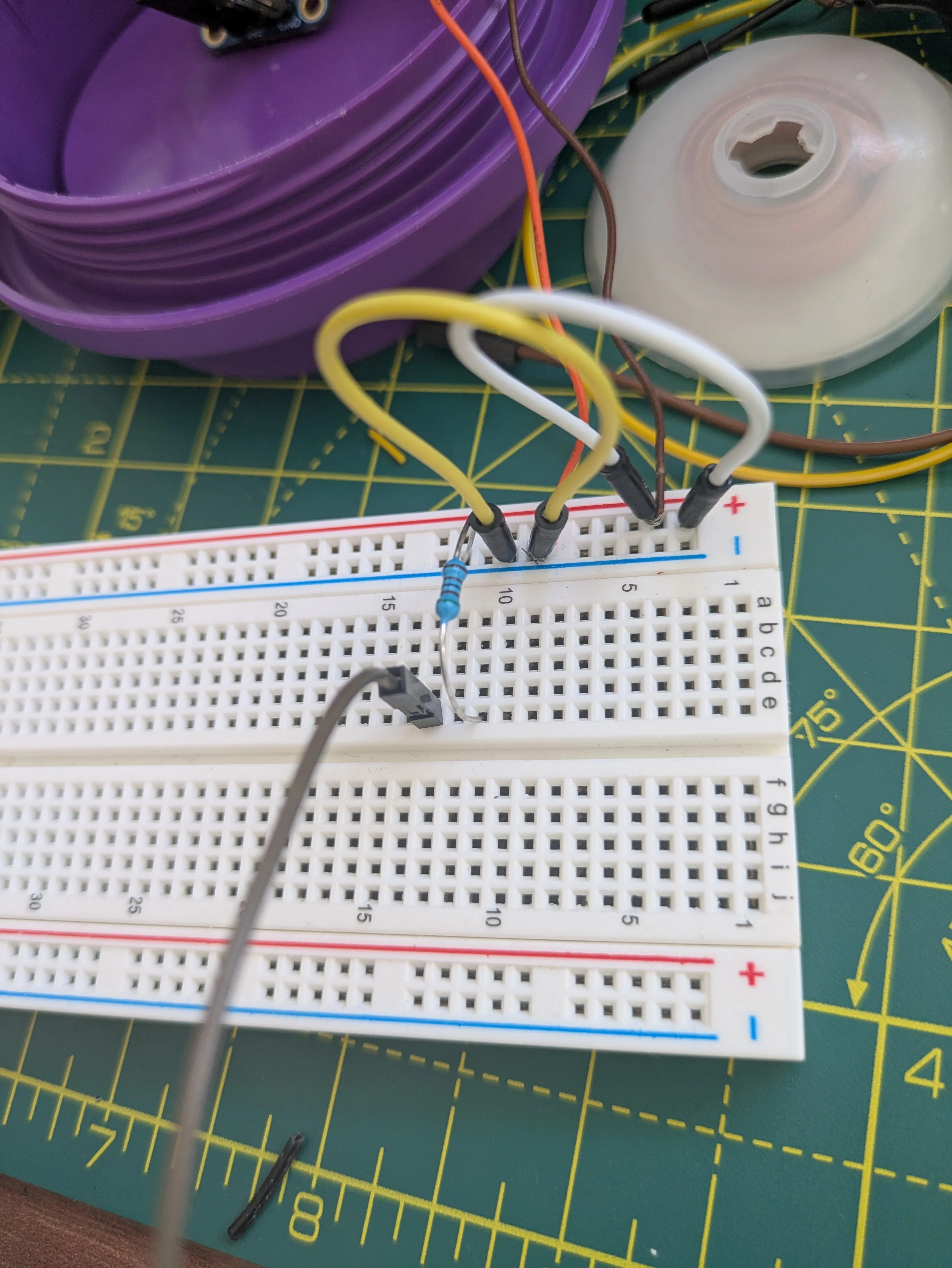
The morning’s verdict (episode 17) said the counts were lies and the wiring was the liar. So tonight I stopped patching the old rig and did the thing you’re supposed to do from the start: tear it all down and rebuild on a bare breadboard, one wire at a time, with the meter confirming every step before the next one goes in.
Dedicated 5 V onto the rails: 5.00 V. Same 5 V at the sensor’s own solder pads — so the
power chain was honest end to end. Then the dividers, and that’s where I had to eat
something.
All this time, my “divider” resistors sat in series — between the encoder wire and the
GPIO — because in my head a resistor in the path protects the pin from 5 V. It doesn’t.
A GPIO input draws essentially no current, and Ohm’s law is merciless about it: no current,
no voltage drop. The full 5 V had been sailing through my “protection” and arriving at
pins rated for 3.6 V absolute max, the whole time. What actually divides voltage is a
resistor chain that current flows through — one from the signal, one down to ground, pin
tapping the midpoint. I knew that shape from diagrams. I’d just built a different one.
Then the new divider refused to divide — 5 V barely sagged to 4.97 V — and that broke
a second assumption. The firmware’s own comments said these outputs idle high through an
internal pull-up. They don’t. They’re push-pull: the sensor drives the line hard in
both directions, and a shunt resistor alone can’t argue with it. The fix is the classic
two-resistor divider (2k in series, 2k+1k to ground), which finally metered a safe,
solid 2.94 V at both nodes.
The rebuild had its comedy. I metered “5 V” between two systems that shared no ground wire
and learned that a voltage between two floating islands is a measurement of nothing. I
plugged a rail jumper into the pin next to GND — which is VIN — and briefly fed 5 V into
my own ground bus. A magnet press jolted a shunt resistor’s leg loose and one node crept
to 4.40 V while connected to a pin; the series resistor quietly capped the current and
the pin lived. Every one of these mistakes got caught by the same boring discipline:
meter it, then connect it.
And then the payoff. With the circuit finally known — not assumed, known — I pressed the magnet on the two hall chips and watched the live stream: channel A fired. Then channel B fired. B — the channel that has read zero since the very first session — put ten clean edges on the counter through the entire new chain. Both sensors work. And the full test battery came back silent everywhere it should be silent: zero phantom edges at every duty, both directions, where the old wiring screamed fifty thousand a second. The electrical war is over, and we won.
Which leaves the one part that never joined the party. Drive the motor, disc spinning right past two proven-working sensors: nothing. Run a magnetised screwdriver over those same sensors: counts. The disc — the little brown ferrite ring whose alternating poles are the entire point of the encoder — isn’t putting out enough field to trip its own chips. That’s the whole remaining fault, cornered on a circuit I now trust completely.
One uncomfortable footnote: ferrite pole patterns are exactly the kind of thing a strong magnet erases, and that disc has had a booster magnet stacked on it and a magnetic screwdriver dragged over it more than once today. Some of that may have been self-inflicted. The strong magnet and the disc are separated permanently now.
Next session is short and decisive: plug the second motor’s encoder into this proven rig and hand-turn its disc. If it counts, I’ve confirmed the diagnosis and I’m holding a working spare. And the logic analyzer that’s already in the post gets clipped straight onto A and B — no firmware, no divider, just the raw truth off the wire.