Blog / Neato D10 Brain Transplant / Ep. 17
episode 17
Fifty thousand lies a second
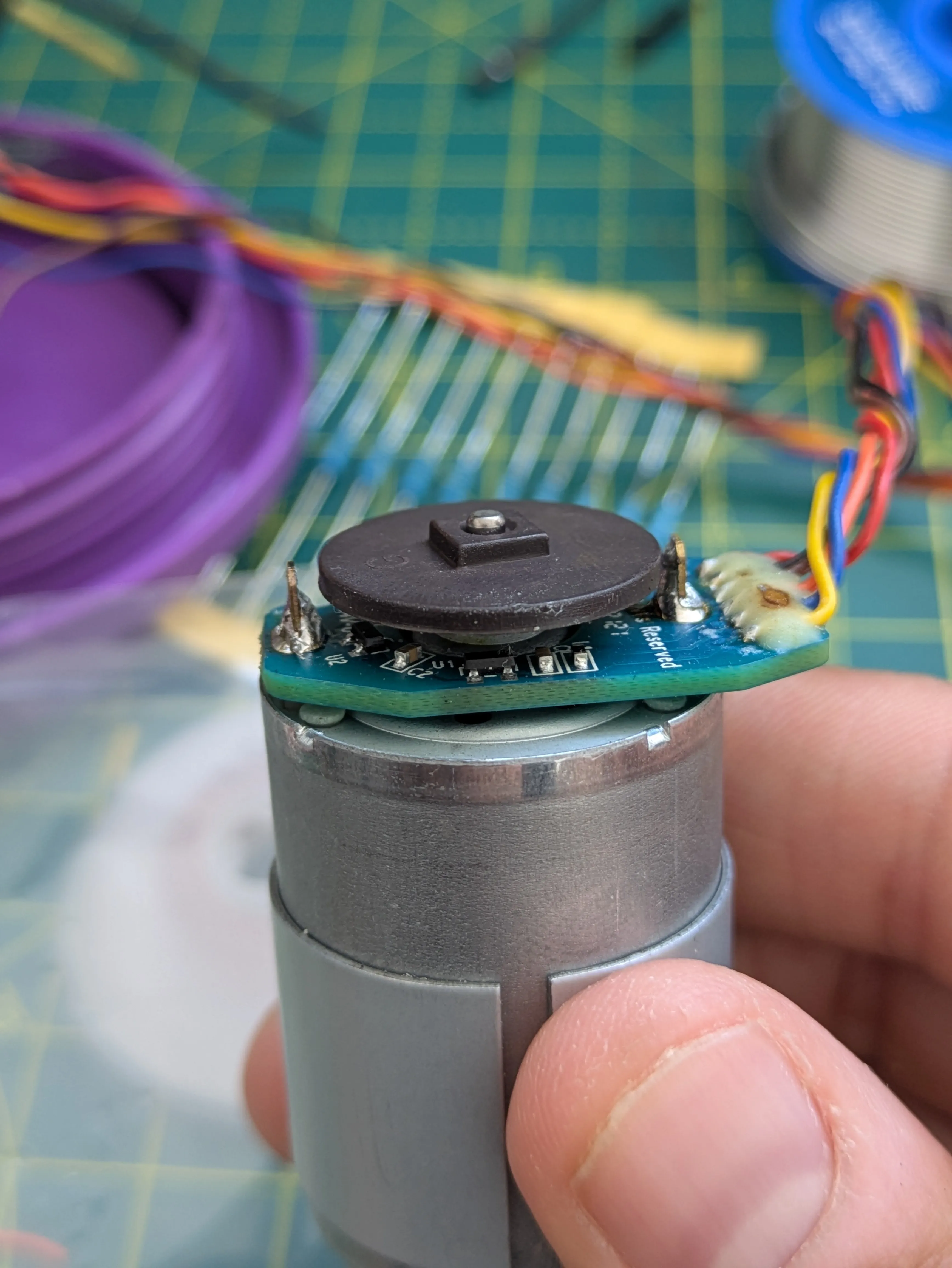
This one’s a running investigation log — I’m updating it as findings land rather than
writing it once at the end. The hard evidence lives next to the tool, in
hardware-scripts/test-scripts/hall-probe/ENCODER-DIAGNOSIS.md.
Where this picks up
Last episode ended with a theory and a promise: the encoder wasn’t dead, a shared solder joint had probably cracked, and next session I’d reflow it and win my 422 edges back.
Today started so well.
The resurrection
I found a magnet — well, a screwdriver with a magnetic bit holder, which is the kind of lab equipment this project deserves — and waved it over the sensors. Channel A woke up. Level flipped, counts climbed, exactly like a live hall sensor should. Then, after some fiddling with the magnet’s position, channel B started counting too. Both channels alive. The solder-joint funeral was cancelled.
And then it got better: I drove the motor and both counters took off. A climbing, B climbing, position swinging. After two sessions of dead silence, the robot was suddenly chatty. I pasted a screenful of rising numbers into the session feeling pretty good.
I should know by now that this project punishes feeling pretty good.
The numbers were wrong in a specific way
The counts were climbing, but they were climbing strangely. One run, A counted 1.6× more than B. The next run, B counted 1.9× more than A. A quadrature pair is two views of the same rotation, 90° apart — they should tick at the same rate, every run. And the position value, which should march steadily in one direction while driving one direction, was random-walking: −6, +154, −104, back again. Direction decode was producing noise.
Then two bench facts landed that broke the case open:
Fact one: the magnet disc doesn’t start spinning from rest until duty ~150 — stiction. Below that, the motor hums and nothing rotates.
Fact two: a test run at duty 80 — below stiction, disc provably not moving — logged seventy thousand edges.
Seventy thousand edges from a magnet that never moved. There was only one honest reading of that: the counts had never been measuring rotation at all.
Catching it red-handed
So I stopped tinkering and built an interrogation. A small test battery
(diag/quad-diag.py — new script, its README says what each phase captures) designed
around the stiction fact, because that fact turns “is it noise?” into a controlled
experiment: any edge at duty < 150 from rest cannot be real.
The results, in the order they twisted the knife:
- Motor off, 8 seconds: zero edges. Perfectly quiet.
- Duty 40 / 80 / 120 — disc still: ~46,000–52,000 edges per second. All phantom.
- Duty 200 — actually spinning: ~23,000 edges/s. Less than not-spinning at duty 40. The counts track PWM activity, not motion.
- The kill shot: drive at 220, then cut the motor and keep watching while the wheel spins down. The instant PWM stops, the edges stop — 7,425 in the last half-second of PWM, then zero — while the wheel is still physically turning. Real rotation, with the noise source off, produces nothing.
- Brake at rest: zero. Both quiet H-bridge states are silent.
- Reverse: same noise signature as forward; position doesn’t flip sign, because there’s no real signal to decode.
Every big number I’d celebrated today was electrical noise from the motor’s PWM, arriving at tens of thousands of lies per second. The only genuine edges in the whole saga were the handheld-magnet tests with the motor off — small, discrete counts with clean level flips.
Why it happens
The culprit was hiding in arithmetic I’d already written down and never done. The encoder board pulls its outputs up to 5 V through an internal ~2.4k resistor. My 3.3k-to-GND divider — there to keep 5 V off the ESP32’s not-5V-tolerant pins — parks the idle-high level at about 2.9 V. The ESP32 doesn’t promise to read a pin as high until about 2.5 V. That’s 0.4 volts of headroom, on unshielded wires running next to motor leads carrying hard PWM switching edges. Every scrap of coupled noise that dips the line below threshold is a “falling edge”; the bounce back is a “rising edge”. The firmware counts every single change, no questions asked — because I wrote it that way.
I also got to bin a couple of theories properly, which is its own satisfaction. A saturated sensor (my leading suspect at lunchtime) would pin its output and go silent — saturation can’t invent counts, and everything here is silent until the PWM starts. And the pull-up resistor the classic hall-sensor wiring diagrams show between 5 V and the output? Already there, inside the encoder board. Not missing.
The lesson (this week’s edition)
Last episode’s lesson was that every honest reading can still be a red herring. This episode’s is sharper: a counter that counts is not evidence of the thing you built it to count. I spent half a day treating “the numbers go up” as “the encoder works,” when one control experiment — run it below stiction, where nothing can move — falsified that in ten seconds. The control was free the whole time. I just hadn’t thought to ask for it.
Update, same afternoon: the filter that failed, and what the failure taught
I said the cheapest next move was a firmware glitch filter, and I got called on it —
rightly — with a version of “you have the hardware, why aren’t you testing that claim?”
So the firmware grew a runtime command: G 50 sets a 50-microsecond glitch filter,
G 0 puts everything back exactly as it was. Flash, sweep, measure.
First attempt: a spacing filter — ignore any edge that lands too soon after the last accepted one. Result: complete failure, and a beautifully instructive one. At every setting, the accepted rate was exactly one-over-the-window: 200 µs → 5,000 edges/s, on the dot. The filter wasn’t removing the noise; it was metering it. Which means the noise isn’t occasional spikes — it’s continuous. Whenever the window expired, another false edge was already waiting.
Second attempt: a stability filter — a new pin state only counts if it’s still there X microseconds later. This one discriminated, and the pattern it revealed cracked the mechanism open: a 10 µs filter annihilated the noise at duty 200 but passed the noise at duty 80 completely untouched. The false dips are as wide as the PWM off-time — 11 µs at duty 200, 34 µs at duty 80. The encoder line isn’t picking up little spikes. Its entire reference level is moving with the chopped motor current — through the shared ground wire, where the encoder’s ground and the motor’s return current ride the same copper. Ground bounce. The wiring diagram had the culprit in it the whole time, labelled “common — REQUIRED”.
So: software cannot fix this. Both filter designs are dead ends, and I can prove it rather than suspect it.
Then the endgame experiment. At duty 255 the PWM stops switching entirely — the line is just on — so the electrical storm should stop while the disc spins at full speed. It did: phantom edges collapsed a thousandfold, forty-eight thousand a second down to forty-three. And those last forty-three? Bucketed over time, they all sit in the first second — the inrush surge while the motor spins up. At constant speed: zero. Through a three-second coast: zero.
Zero. The disc was spinning as fast as it will ever spin, past two working sensors, and neither one noticed. Every genuine edge this encoder has ever produced came from a magnet in my hand, point-blank. The spinning disc’s own field never once reached across the air gap with enough strength to trip anything.
Where the investigation actually stands
Three layers, all proven now, each one hiding under the last:
- The counts were noise — one phantom edge per 20 kHz PWM cycle, per channel.
- The noise is ground bounce — motor return current through the shared ground wire, un-fixable in software (proven twice), fixable with star grounding and decoupling.
- Under the noise: nothing. The real rotation signal is zero. The original problem — the disc’s field never reaches the sensors — was there all along, waiting behind the fireworks.
The full hypothesis ledger — eleven hypotheses, the experiment that tested each, what
survived — lives in hardware-scripts/test-scripts/hall-probe/diag/HYPOTHESES.md.
Next session needs hands, not code: rewire the grounds star-style, close the air gap, and check the disc actually has alternating magnetic poles around its rim. Then the same battery decides: below-stiction must read zero, and a coast must show real edges dying slowly with the wheel. That’s what truth will look like.
The investigation concluded the same evening — the full teardown-and-rebuild, the resistor confession, and the final verdict are episode 18: “One wire at a time.”