Blog / Neato D10 Brain Transplant / Ep. 12
episode 12
The answer wasn't on the workbench
The power stage arrived. All of it — two DRV8871 wheel drivers, the Cytron MD13S for the roller, the little MOSFET module for the side brush, even the speaker amp. Every motor on this robot now has something to drive it sitting on my bench. This should have been the session where I wired a real wheel up and watched it turn. Instead I got sidetracked by the cliff sensors, and I lost.
The easy wins came first. The bumper switch: meter on continuity, press the bumper, it beeps — normally-open, so a press pulls the line LOW. That’s “I hit something.” Then the wheel-arch “dead-man’s” switch, the one that catches the robot being lifted or hanging over a stair edge. I had the mechanics backwards — I assumed the wheel presses the switch when the robot’s sitting on the floor. It’s the opposite: on the ground the wheel’s held up and the lever sits open; lift the robot and the wheel falls, and the fall is what clicks the switch closed. So “lifted” reads LOW, same polarity as the bumper. One code path handles both. Tidy.
Then the cliff sensor. LOUIE DRP 290-1023. A downward IR eye — two clear windows behind a dark bezel, an emitter and a phototransistor. Five wires into a JST connector the size of a grain of rice. The plan was obvious: diode-test the wires, find the ~1.1 V LED, read off the pinout. Twenty minutes, tops.
It was not twenty minutes. First fight: the connector’s too fine-pitch — female Dupont housings are fatter than the spacing, so every one I pushed on shoved against its neighbour. Second fight: sewing pins jammed into the sockets, meter probes skating off them. Third fight, and I was proud of this one — plug the sensor back into the old mainboard, which has fat connector pins poking through the back, and clip onto those. Finally, readings! 1.998. Then 0.485. Then 0.354. Real numbers.
Real, and worthless. Four pins reading nearly identically to one common pin isn’t a sensor — it’s the old board’s ESD protection diodes, all tied to a shared ground plane. I was carefully measuring the board I’m throwing away.
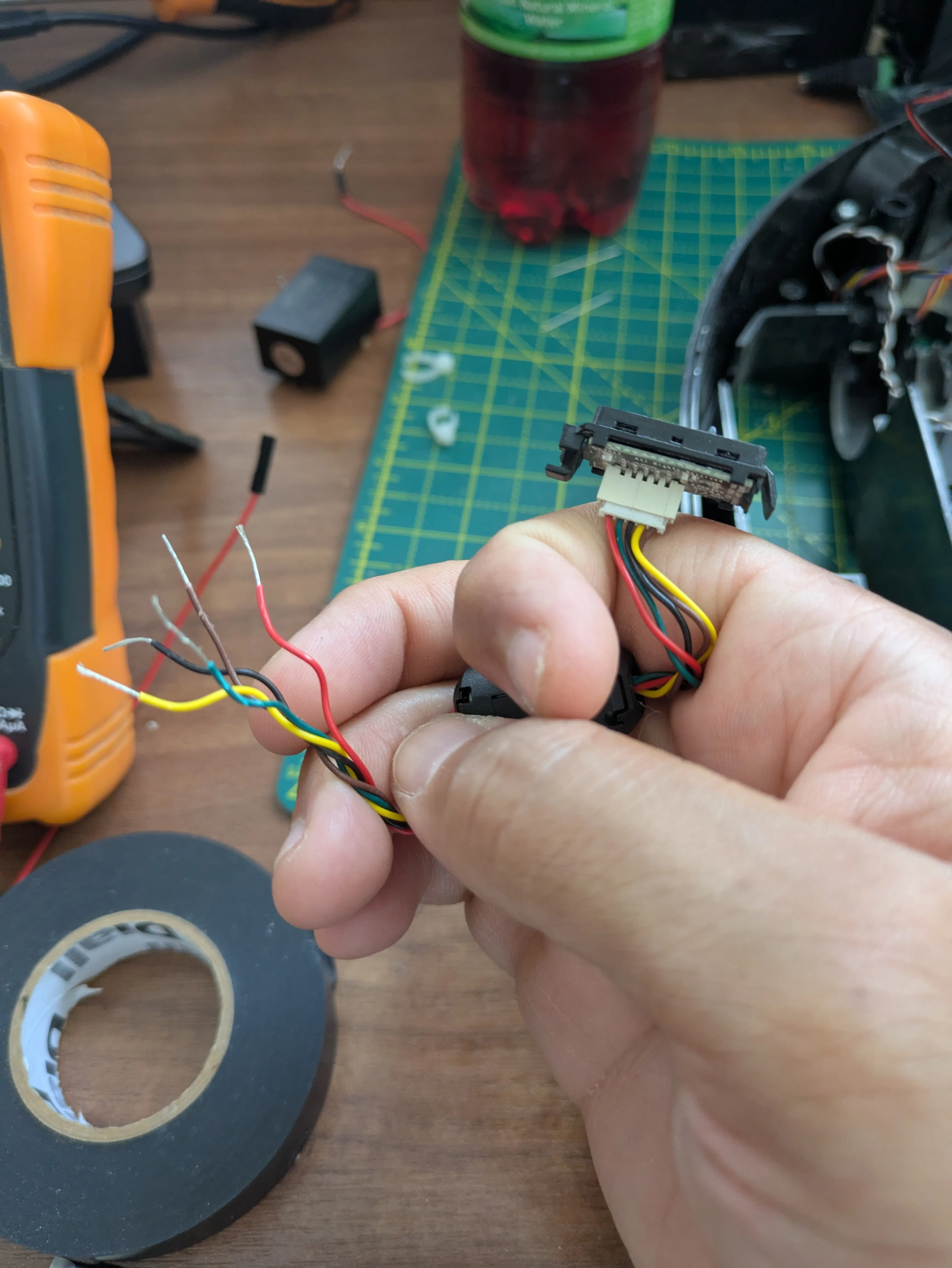
So I cut the harness. Kept the sensor and its native plug as a pigtail, snipped near the far end, stripped five clean tails of bare copper. No board, no fine pitch, nothing to slip off. Diode test, one more time. And each pair flashed 1.758 for a heartbeat, then snapped back to 1 — open circuit. Every pair, the same. That’s not a diode. A diode clamps and holds. That flash-then-open is a capacitor charging up — there’s a decoupling cap on the board swamping the whole test.
Three tools, three different lies. And that was the turn: the answer was never going to come off my meter. So I stopped poking and looked it up.
The 290-1023 is the stock Botvac D-series drop sensor. It’s sold as a two-sensor set on one cable — which quietly confirmed my own finding that two of them gang into that 10-pin connector. Every tester reports the same convention: black is ground, red is power, and the signal swings 0–3 V. A 0-to-3-volt swing means it runs on about 3.3 V — which is exactly the thing I’d spent all afternoon failing to measure. It wires straight to an ESP32 ADC pin. No level shifter. And the part that made me laugh: the emitter is strobed by the host and the phototransistor read in sync, to reject ambient light. It was never designed to be read statically with a meter. Of course my DC test died — I was holding a steady voltage against a thing built to be pulsed.
One forum thread insisted the sensor was a Sharp module — but that’s the wall sensor, a different part. And then the best moment of the day: I pulled the robot’s actual side/wall sensor and it’s got the same LOUIE DRP silkscreen on it. Same board. One sensor type covers both the cliff and the wall. Eyes on the real part beat the forum’s guess.
So I never did get a clean reading off that sensor. But I know more than a reading would’ve told me — the voltage, that it’s analog, that it needs no shifter, how the factory actually drove it, that they come in pairs, that the wall sensor is the same board. That’s characterised. The one scrap left — which of the three coloured wires drives the emitter and which carries the signal — is a ten-minute job for later: power it up, point a phone camera at the window (IR glows on a phone sensor), and watch which wire lights it.
The drivers are on the bench now, unopened, waiting. Next session is the one I’ve been circling for eleven episodes: a real Neato wheel motor, a DRV8871 that can actually stomach its 2 A stall, and an encoder wired to the back — so the wheel doesn’t just spin, it tells me how far it went.