Blog / Neato D10 Brain Transplant / Ep. 11
episode 11
The first thing that moved because I told it to
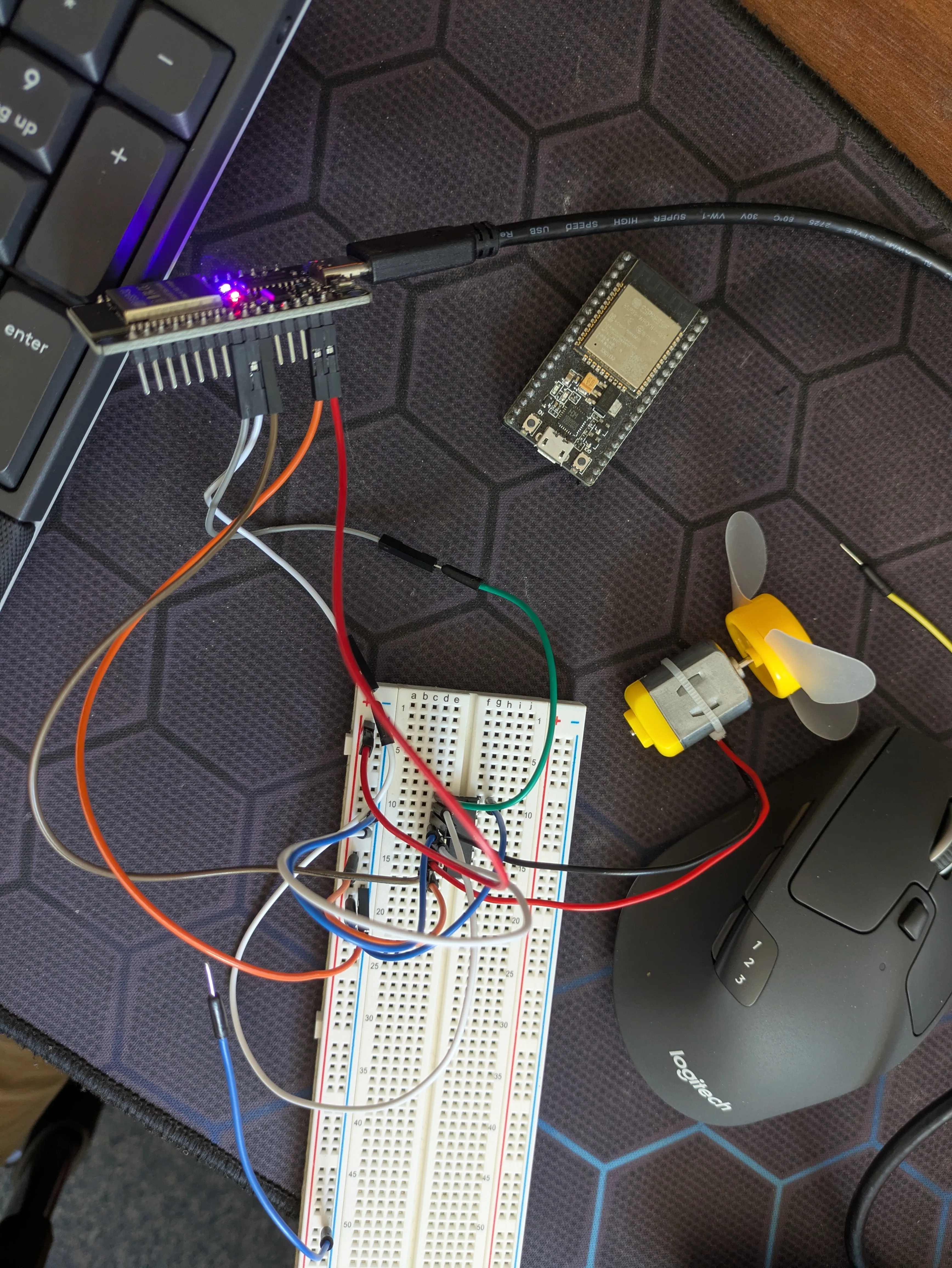
Ten episodes in, and everything so far has been reading the robot — cracking it open, metering motors, arguing with datasheets, buying parts. Not once had I made any of it do something. Today a padded envelope showed up with two ESP32 boards in it, and the plan finally had a verb in it: make a motor spin because I said so.
The very first thing was smaller than I expected. Before any motor, before any wiring, I just wanted the Mac to see the board. Plugged it in over USB-C, and — no driver drama, macOS has shipped the CH340 driver for years now — it turned up as a serial port. Then a small comedy: I fired the chip-info read and got No serial data received, three times. Classic “wrong port.” There were two usbserial devices and I’d been talking to the wrong one the whole time — some pre-existing adapter, not the ESP32. Pointed the tool at the right one and it answered instantly: ESP32-D0WD-V3, dual core, 4 MB flash. Auto-reset over the RTS line worked too, which meant I wouldn’t have to do the hold-BOOT-tap-EN button dance to flash it. Small mercies.
I went with PlatformIO rather than the Arduino IDE, because the endgame here is micro-ROS and PlatformIO is the smoother road there. First build pulled down the whole Xtensa toolchain — 110 seconds — then flashed a little firmware that blinks the onboard LED and echoes anything I type back at me. That echo isn’t a toy: it’s the exact two-way serial channel that’ll carry motor commands later. Solid red power light, a blue LED blinking under D2 once a second — that blue blink is my code, looping. It was alive.
Now the actual point: serial command → ESP32 → H-bridge → motor. The rule I set myself up front — and it matters — is that the real Neato wheel motors stall at over 2 A, and the little L293D bridge from my Elegoo kit maxes at about 0.6 A a channel. Put a real wheel on it and you cook the chip. So this step uses a small hobby DC motor as a stand-in. The goal was never to spin the real wheel today; it was to prove the chain works before the proper drivers land.
The board my kit came with labels its pins D25, D26, D27 — no “GPIO” printed anywhere, which had me hunting for a second before the penny dropped that D just is GPIO. I mapped it out on the breadboard: three signal wires (PWM speed, two direction pins), logic power off the ESP32’s VIN, motor terminals across the bridge, everything sharing one ground rail.
Then it didn’t work. Typed F 150, and — nothing. Not a twitch.
This is where the meter earns its keep again. The ESP32 was clearly fine — still blinking, still acknowledging every command over serial. So the fault was on the bridge side. I probed the L293D’s two supply pins. Pin 16, the logic supply: a wobbly 3.84 V, not great. Pin 8, the motor supply: 0.57 V. Basically zero. No power to the motor at all — of course it didn’t move.
And here’s the honest bit. Pin 8 wants a separate feed for the motor, and I’d been quietly assuming a battery I didn’t own and had never actually been told to get. It was never on any parts list. I’d narrated “motor battery” to myself like it was obvious. It wasn’t.
The fix was almost embarrassingly simple: this stand-in motor is tiny, so I didn’t need a battery at all — I just fed the motor side from the same USB 5 V, turning one rail into a shared 5-volt bus. Re-metered: pin 8 now 4.65 V, pin 16 steady. Yes, the L293D drops a volt and a half or two internally, so the motor would only see around 3 V — but that’s plenty for a small motor, and plenty to prove a point.
F 200.
It spun.
I’ll be honest about how that felt after ten episodes of reading — I typed a word on a keyboard and a physical thing in front of me turned. Then I ran it properly: F 130, F 200, F 255 — you can hear it climb — a stop, then R 200 and it spun the other way. Speed control and direction, both, from typed commands. I stuck the little fan blade on it to make the reversal visible, felt the air blow one way then get sucked the other. My son wanted to see it, so I made it dance.
None of the electronics I’ve bought have arrived yet — this ran on a stand-in motor and a bridge too weak for the real job. But every layer underneath is now proven: the toolchain, the serial channel, the PWM, the H-bridge pattern. That’s exactly what the DRV8871 drivers will do to the real wheels when they land. Which is the next thread: a real Neato wheel motor, a driver that can actually feed it, and — this time — an encoder on the back, so the robot doesn’t just move, but knows how far.