Blog / Neato D10 Brain Transplant / Ep. 8
episode 8
The motor that wasn't on the list
Every previous session had left me one measurement short of ordering the motor drivers. The roller brush was the last gate: a slightly different motor from the wheels, no current printed on it, and until I knew what it pulled I was guessing at which driver to buy. So this session had a simple, satisfying shape — measure the brush, count a couple of harness wires I’d been meaning to check, and hit “buy.” A tidy afternoon.
It did not stay tidy. But let me give you the tidy part first, because it went well.
The roller brush is a beast. Alligator clips on the two chunky terminals, rotate the shaft, let it settle, take the lowest stable reading: it sat between 2.0 and 2.3 Ω. Subtract the 0.1 Ω of lead resistance and call it 1.9 Ω, and Ohm’s law does the rest: stall ≈ 14.4 V ÷ 1.9 Ω ≈ 7.6 A. That’s a different animal from the drive wheels, which came in around 2.1 and 2.4 A. The brush pulls three times as much. Any thought of a dainty little MOSFET for it evaporated — this one gets a BTS7960, which shrugs off that kind of current. Gate cleared.
And a bonus while I was in there. The brush motor doesn’t just have two power wires — it has two thick ones and three thin ones. Those three are a Hall tacho: power, ground, and a signal line that ticks as the brush spins. Which means I can watch the brush’s speed, and a brush that suddenly slows is a brush wrapped in hair. Free jam detection, straight into an ESP32 pin. I’ll take it.
Then the wheel harness, which paid off. I’d been carrying an open question for weeks: how many wires come off each wheel? Five would mean a single-channel encoder — I could count how far the wheel turned but not which way. Six means quadrature: two channels, direction-aware, exactly what the mapping software wants so it doesn’t get confused when a wheel backs up. I reopened the chassis — mind the reverse-threaded axle screw, lefty-tighty — traced two thick red-and-black wires to the motor posts, and counted the rest into the encoder puck. Four. Two plus four is six. Quadrature. The good answer.
So far, so on-script. Three-driver order, ready to send: two DRV8871 for the wheels, one BTS7960 for the brush, nothing for the smug self-driving blower — and I confirmed its four wires while I had the lid off, so that stays settled.
And then I looked at the underside and felt slightly stupid. There’s a little brush that sticks out past the D-shaped front edge — the spinning one that flicks debris in from the corners toward the suction. It has a motor. It has always had a motor. And it is nowhere in my notes. My whole build doc was written around “four motors,” and somewhere back at the start I’d simply never counted the side sweeper. “Full vacuum function” was quietly a five-motor problem the entire time, and I was one click away from ordering for four.
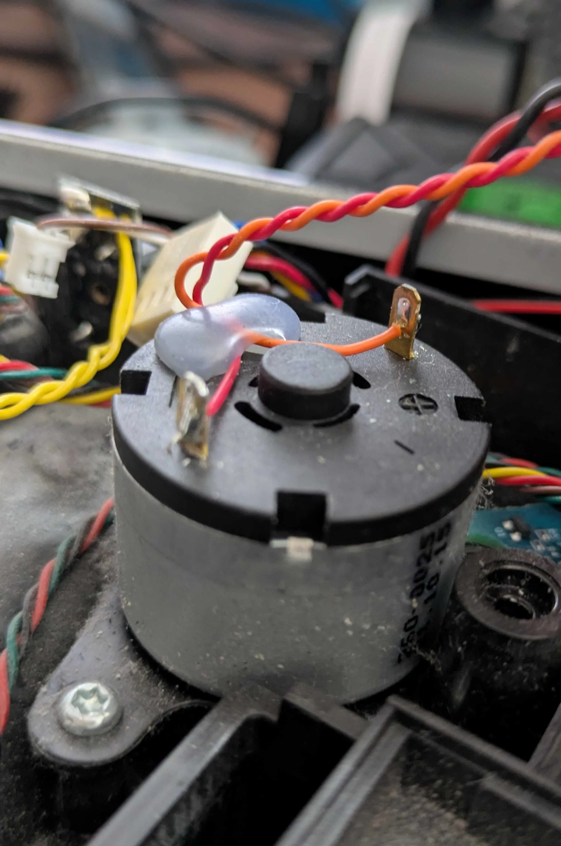
So I photographed it and clipped the meter on. Small black can, two wires soldered straight to the tabs, a little blue suppression cap across them — a plain brushed DC motor, no sensor, spins one way. And where the roller read a beefy 2 Ω, this one read 20 to 30 Ω — small motors run the scale backwards, more winding, less current. 14.4 V ÷ 20 Ω ≈ 0.7 A. Nothing, basically. Too small to earn its own big driver, too awkward to share a channel with anything else, so it gets a cheap little MOSFET module of its own and a PWM line from the ESP32.
Which makes the final tally five motors, four drivers, one order:
2× DRV8871— drive wheels1× BTS7960— roller brush1× MOSFET module— side brush- blower — still needs nothing, still smug
Plus the buck converter to feed the logic off the 14.4 V pack. Every motor on this robot now has a measured number next to it and a part picked to match. The teardown is genuinely finished. The next box that arrives isn’t another tool — it’s the ESP32, and the first time I try to make one of these motors spin on purpose.
I just have to remember, this time, to count all five.
Postscript: the number that wouldn’t sit right.
I published that list with a BTS7960 next to the roller brush and then couldn’t leave it alone. The BTS7960 is a 43-amp module. My brush stalls at seven. Sizing to stall is the rule, sure, but six-times headroom felt less like engineering and more like buying the biggest thing on the shelf and calling it caution.
Then a better instinct landed: there are no chunky capacitors on the Neato board I’m gutting. If this motor really needed 43 amps of driver, the original design would show it — fat caps, thick copper, a beefy driver chip. It doesn’t. Which is the clue: my 7 A is stall, the once-in-a-jam worst case. The brush runs at maybe an amp. The original board just current-limits the stall and lets the big battery soak up the spike — no cap bank required. I was sizing for a number the motor almost never sees.
So I went looking for what Neato themselves used, and the reverse-engineering community had it. The old XV-11 bill of materials lists the drive-motor driver by name: an Allegro A3950, a full-bridge rated about 2.8 amps. That’s it. Neato ran the wheels on a ~3 A part — and my wheels measured 2.4 A stall, with the DRV8871 (3.6 A) sitting right on top of it. Not overkill. Correctly sized, confirmed by the people who built the thing. And nowhere in that BOM is there a 43 A monster. The brush got simple MOSFET-class drive. My gut and their schematic agreed: the BTS7960 was too much.
The brush only spins one way, and the original had no unjam-reverse trick, so a plain logic-level MOSFET would do the job — with one trap I nearly walked into: the common IRF520 module isn’t actually logic-level, and a 3.3 V pin can’t fully switch it. You want an IRLZ44N-class part that a microcontroller can turn hard on.
But here’s where I landed, and why I didn’t just go all-MOSFET: the roller is my highest-current channel, it runs hottest, and it’s buried in a chassis I’ll hate reopening. For about a fiver more, a Cytron MD10C — a proper 10 A motor driver — brings reverse-polarity protection, a real gate driver that switches cool, and freewheeling built in. It’s the difference between a bare switch I have to protect myself and a driver that protects itself. On the one channel most likely to bite me, that’s cheap insurance. And it’s bidirectional — so that auto-unjam feature the robot never had? The Pi’s got the brains and the brush’s got a tacho. I can add it in software later, spin the brush backwards to cough out a hairball on its own. A feature the original never shipped, for free, because I sized the driver like an engineer instead of a shopper.
The tiny side brush keeps its little MOSFET. 0.7 A doesn’t need protecting from anything.
Final list, for real this time: 2× DRV8871, 1× Cytron MD10C, 1× logic-level MOSFET, one buck converter, nothing for the smug fan. Now the teardown’s finished.