Blog / Neato D10 Brain Transplant / Ep. 5
episode 5
A number that wouldn't sit still
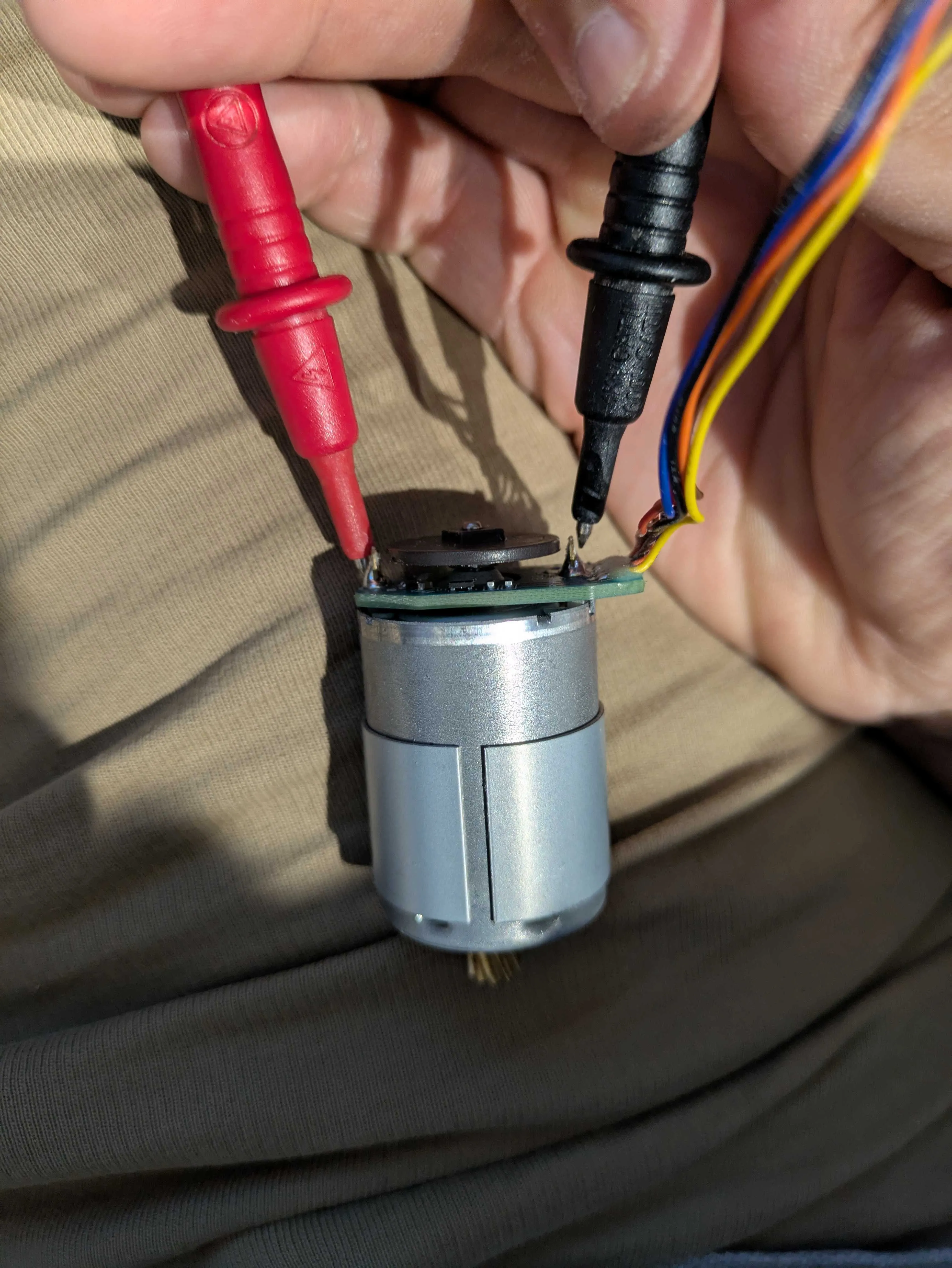
Last episode I decided to stop trying to catch a stall spike on a cheap meter and measure winding resistance instead — no power, just Ohm’s law, stall ≈ 14.4 V ÷ R. Clean idea. This episode I actually did it, and the bench had opinions.
First, an apology to my own multimeter. Last time I called its 10 A jack unfused and used that as a reason to avoid current mode. I picked the meter up to check something and there it was, printed right on the panel: MAX 10A FUSED. So the scary “unfused short across a Li-ion pack” I’d talked myself out of? Not a thing on this unit. It doesn’t change the plan — resistance is still the better method, because a 2000-count meter still can’t see a millisecond inrush no matter which jack it’s in — but the record needed correcting. Measure twice, blog once.
Then the actual measuring, which went badly before it went well.
I shorted the probes to get my lead resistance: 0.1 Ω, fine, subtract it from everything. Then I put the probes on the left wheel motor and got 39.9 Ω. That’s nonsense for a motor winding — they live around 1–5 Ω — so I took a photo of where my probes were sitting and looked properly. The black probe was parked over by the thin coloured encoder wires. I was measuring through the encoder board, not across the winding. The motor terminals are the two chunky solder posts flanking the disc; the encoder is sensing-only and carries no motor power. Wrong two points entirely.
So I moved to what I thought were the right posts and got 1 — a lone digit on the far left of the display, which on this meter means open circuit. No connection at all. I’d overcorrected onto an isolated pad.
At this point I’ll be honest: I wondered if I should desolder the encoder board to get at the motor terminals cleanly. Good instinct to check, terrible idea to do — that board is the wheel odometry the whole ROS navigation stack leans on. It stays. And I didn’t need to remove it anyway; the winding is right there across those two chunky posts if I actually land on them.
I flipped to continuity mode — the beeper — as a hunting tool. Sweep the black probe around, listen for the beep that means “connected.” It beeped, and showed 20. That told me I’d found a connection, but continuity mode is a go/no-go tone, not a trustworthy number. Back to the 200 Ω range, and there it was: 20.1 Ω, but bouncing — jumping up to 40, to 100, dropping back, lingering at 20.
And this is the bit I want to remember, because it nearly fooled me. A motor winding does vary as you turn the shaft — the commutator swaps which coil you’re reading — so some bounce is real and you take the lowest. But a bad contact bounces too, and it bounces far more. My 20-to-100 swing wasn’t the motor. It was my hand-held probe tips making and breaking on an oxidised post. 20 Ω would’ve implied a gutless 0.7 A stall motor, which didn’t smell right for something that has to shove a robot over a threshold.
The fix was embarrassingly simple: alligator clips. Clip on, hands off, and suddenly the reading dropped and held at 6.8 Ω. Rotating the shaft mid-grip still threw garbage — one twist flashed 0.8, another went open — but those were the clips shifting, not the coil. The trick, once I clocked it, was to rotate, stop, let it settle, then read. Do that at a handful of positions and the numbers stop lying and start clustering.
Left wheel settled in a 6.8–9 Ω band. Taking the lowest solid reading: R ≈ 6.7 Ω, so stall ≈ 2.1 A. The right wheel was better behaved from the start — steady between 6.0 and 6.7 — giving R ≈ 5.9 Ω and stall ≈ 2.4 A. Same part number, two readings a hair apart: a matched pair, exactly as they should be.
That number kills my provisional plan. 2 A-ish stall is above what a TB6612FNG wants to carry continuously, so the neat single dual-driver board is out. It’s two DRV8871 boards instead — one single H-bridge per wheel, 3.6 A each, plenty of headroom. Slightly more wiring, but I’m not buying a driver that melts the first time a wheel jams.
One more trap worth flagging, this one purely mechanical. Getting the wheel motor out of its chassis housing meant undoing the axle screw, and it fought me — I was cranking it the “loosen” way and it was quietly doing itself up tighter. The thing is reverse-threaded: lefty-tighty, righty-loosey, the mirror image of everything your hands expect. It’s a sensible bit of engineering (a forward-driving wheel would work a normal thread loose over time), but it absolutely caught me out for a minute. If you’re following along and an axle screw feels like it’s getting worse as you turn it — you’re going the wrong way. Turn it the “wrong” way.
Two down, one to go. The roller brush is a slightly different motor and it’s the last unknown current in the whole robot — measure that, and the entire driver order goes in as one parcel. That’s tomorrow’s first job.