Blog / Neato D10 Brain Transplant / Ep. 20
episode 20
Backwards
The logic analyzer turned up — a cheap eight-channel clone, 24 MHz, the exact boring test I’d
been deferring since episode 19. sigrok saw it straight away, and I wrote a little capture
script that clips onto A and B, watches the raw square waves, and prints an edge count and a
verdict. No ESP32, no divider, no firmware in the loop. Finally, the right instrument for a
sensor that only answers in motion.
I clipped it on, powered the encoder, spun the wheel. Flat. Both channels, dead flat, zero edges. Spun it again — flat. Magnet sweep across the chip — flat. Three, four, five captures, every one identical.
Now, episode 19’s whole lesson was don’t trust a flat reading until you trust the instrument. So this time I did the discipline. I lifted the CH0 clip off the sensor and touched it to ground — and it dropped cleanly LOW. That one test proved the analyzer worked, the channel worked, and my ground was common. Which meant, coldly, that the flat readings were real. The instrument wasn’t blind this time. The sensor genuinely wasn’t switching.
I’ll be honest: I wrote the death certificate. I updated my notes to say the sensors were
dead, decided the disc’s field must have finally given out, and started pricing up the
A3423 replacement. Validating the instrument had made me more sure, not less — which is
exactly how you talk yourself into a wrong answer with a clear conscience.
Then, almost offhand, from the other side of the bench: “wait — I swapped orange and brown on the rails.”
I’d wired the encoder’s power backwards. brown to positive, orange to ground, when it should have been the other way round. A hall sensor powered in reverse doesn’t switch; it just sits there, sulking, drawing a trickle. Every flat capture — the validated analyzer chain included — was correct. It had been faithfully reporting a sensor with no working power. Flip the two wires, twist the wheel, and there they were: edges on both channels, climbing.
And here’s the part that actually stings. When I went back through my own notes, the pinout I’d “confirmed” with a resistance meter a couple of weeks ago — brown = Vcc, orange = ground — was backwards. I’d been carrying a wrong fact around for two weeks and building tests on top of it. The bench settled it the only way that counts: the wiring that makes the sensor produce clean edges is, by definition, the correct wiring. So it’s orange = +5 V, brown = ground. That one’s written on the wall now, in big letters.
With the sensor cleared, I went for the real prize — the ESP32 driving the motor and counting the encoder. That’s odometry. Flashed the firmware and immediately got the thing session 9 could never manage: a dead-clean noise floor. Motor stopped, counters held at zero, no phantom edges. The star ground finally holds.
Then the usual comedy. First run counted on B but not A. Reseated, ran again — counted on A
but not B. A fault that moves between runs isn’t a wrong resistor value, it’s a loose
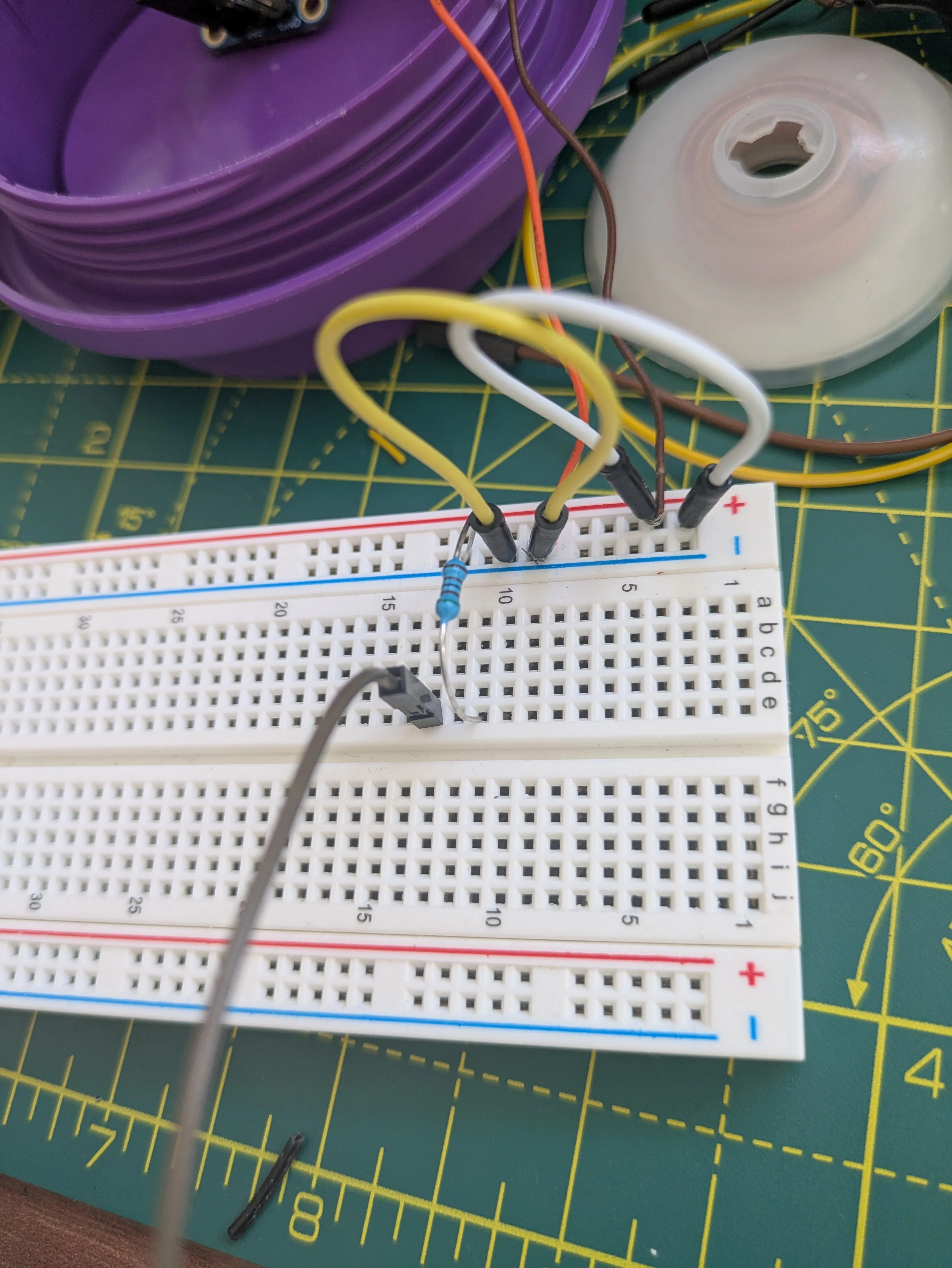
connection — and when I finally looked properly, there were no divider resistors in the board
at all. I’d been feeding 5 V straight into pins rated for 3.3 V, the ESP32’s clamp diodes
quietly saving me the whole time. Built the dividers properly, and both channels counted
together at last.
But pos — the running position, the number that actually makes it odometry — wouldn’t
climb. So I ran the motor at three speeds, and the fault confessed:
- duty
150: A=3088, B=3620, pos = +342 — tracking, clean. - duty
190: pos = +1. - duty
230: pos = −2, and only 110 edges the whole run.
Fewer edges as the motor spins faster. That’s backwards too — and it means the divider is losing edges at speed. The resistors and their long leads make an accidental low-pass filter: slow edges get through, fast ones get rounded off below the pin’s threshold and vanish, and the quadrature decode falls apart with them.
Which is, oddly, great news. At low speed — vacuum speed — pos tracks. The odometry
works. Both channels, direction and all. I started this session ready to bin the sensors and
I’m ending it with confirmed wheel odometry and one clean, well-understood job left: build a
proper low-impedance divider — smaller resistors, short leads, soldered to a scrap of board
instead of dangling off a breadboard — so the fast edges survive too.
Two things I had backwards today: a pair of power wires, and my own certainty. The analyzer was right the whole time. So was the robot.