Blog / Neato D10 Brain Transplant / Ep. 14
episode 14
The corpse in the garage fought back
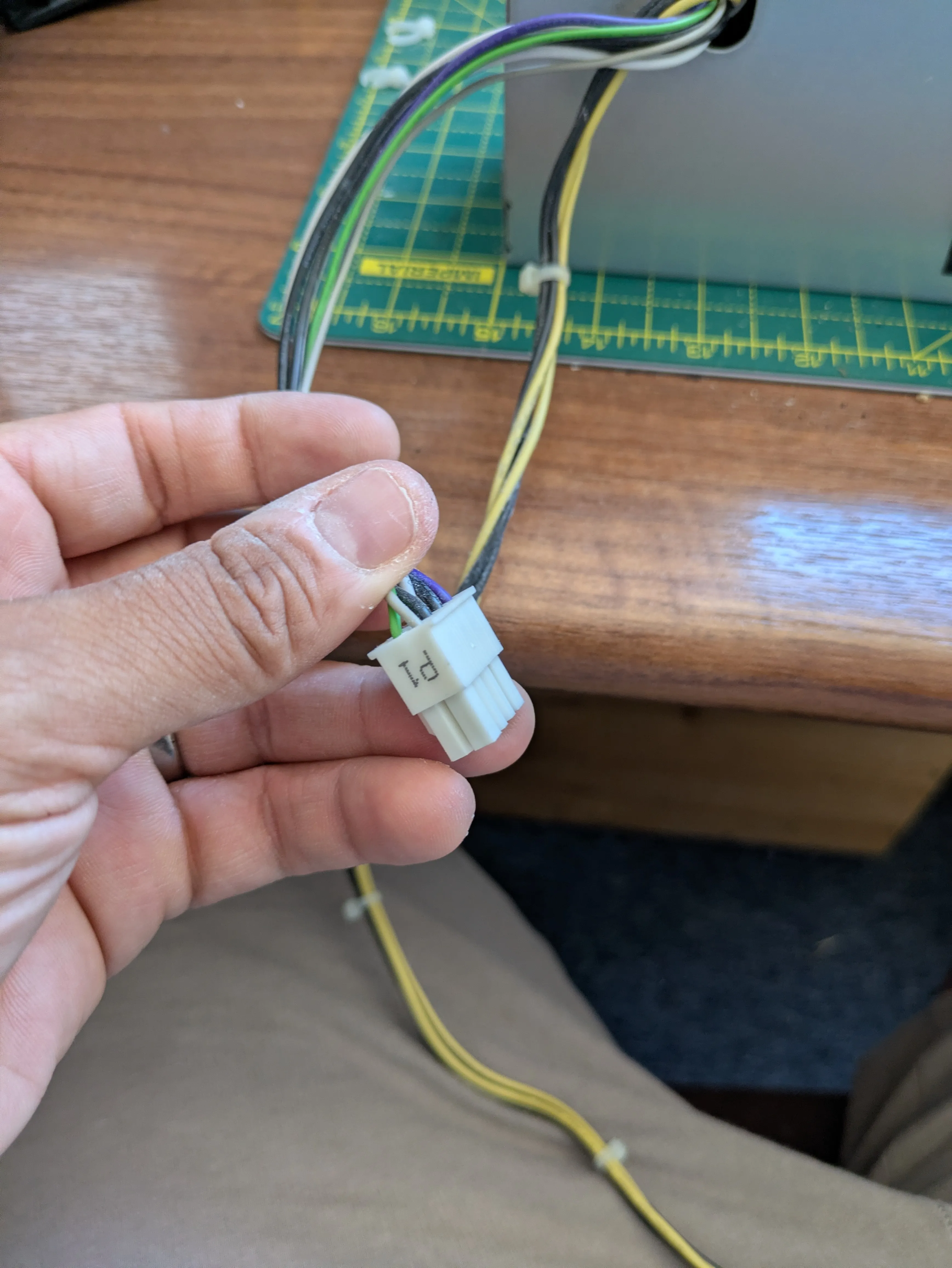
Last session I signed off smug. The dead PC in the garage would give me a free 12 V bench supply for spinning the real wheel motor — everyone knows you jump the green wire to a black one and an ATX supply springs to life. Corpse to the rescue. Easiest win on the list.
Then I actually pulled the supply out and looked at it, and the first thing I saw was the word DELL.
That’s the tell, and I nearly ignored it. Dell’s small-form-factor machines don’t follow the ATX standard on their power connectors — the colours and pins are their own. The famous horror stories are the old ones that reversed the pinout so that jumping “green to black” shorts a rail straight to ground. So instead of grabbing a paperclip I read the label properly: B255ES-01, 255 W, and — the giveaway — an output that’s almost entirely +12V, split across two rails, with barely any 5 V or 3.3 V at all. The main connector confirmed it: not the fat 24-pin rainbow of an ATX supply, but a stubby 8-pin, mostly white and black wires with one lime-green and one purple. Proprietary through and through.
So the meter came out before the paperclip. On a proprietary connector you don’t guess — you verify. The purple wire read 12.04 V the moment I plugged the mains in, before I’d bridged anything: that’s the standby rail, and it told me two things at once — which wire was really ground, and that my read of the colours was right. The whites sat at 0 V, waiting. Then I bridged the lime-green to a black — Dell’s version of the power button — and the fan spun. Whites jumped to 12.0 V. I had my bench supply after all. It just made me earn it, and taught me that “it’s got a Dell sticker” is a stop and read sign, not a grab a paperclip one.
Between all that I had a driver board to build. The DRV8871s came with their screw terminals soldered but the logic header loose in the bag, so — solder it on. I’ll admit the soldering iron and I have a wary relationship, and sure enough the solder kept beading up and rolling off the tip like water off wax. The fix was learning what the little sponge is actually for: the tip oxidises the second it’s hot, and that dull skin won’t take solder. Wipe it clean, and — the bit nobody tells you — press fresh solder on immediately, while the flux in the core is still alive, before it burns off. Shiny tip, and suddenly the joints just flow. Four pins, a continuity check across each pair to prove I hadn’t bridged them, done.
Wiring the motor had one nice puzzle. There were no separate power leads on the wheel motor — the harness runs into the little encoder board first, and the motor’s terminals are soldered to that board. So it’s powered through the encoder. Six wires come out; two are the motor’s 12 V, four are the encoder. Rather than trust the colours I put the meter on continuity, touched a probe to a motor terminal, and buzzed each wire until two lit up: red and black. Those are the motor. The other four I taped aside for later.
And then — of course — it didn’t spin. I typed F 60. Nothing. F 120. Nothing. I did exactly what you do: started re-checking wiring, found I’d swapped two signal pins, felt clever, fixed it. Still nothing. So back to the meter, and the meter cleared the wiring instantly: 12.03 V sitting right on the driver’s motor terminals. Power was there. The board was fine. The wiring I kept re-checking was fine.
It was stiction. A stopped motor needs a real shove to break free, far more than it needs to keep turning, and 60 and 120 out of 255 just weren’t enough torque to crack it off the mark — it sat there humming below the threshold. I sent F 255.
It spun.
Then I ran the full ramp — 120, 180, 255, stop, and R to send it hard the other way — which, on a motor clamped to nothing, made it leap, and made me swear. Full speed control and direction on a real Neato wheel motor, off typed commands, through a driver actually rated for the job. The swapped pins were a red herring; the real lesson is going in the notes for the firmware — the wheels will need a kickstart: a brief full-power punch to break free, then drop to the speed I actually asked for. Otherwise every slow crawl command will just sit and buzz.
The wheel turns because I told it to. But it still has no idea it moved. That’s the four wires I taped aside — the encoder — and it’s next: powering it up, watching two signals dance as I turn the wheel by hand, and finally teaching the robot not just to move, but to know how far.