Blog / Neato D10 Brain Transplant / Ep. 2
episode 2
Cracking it open
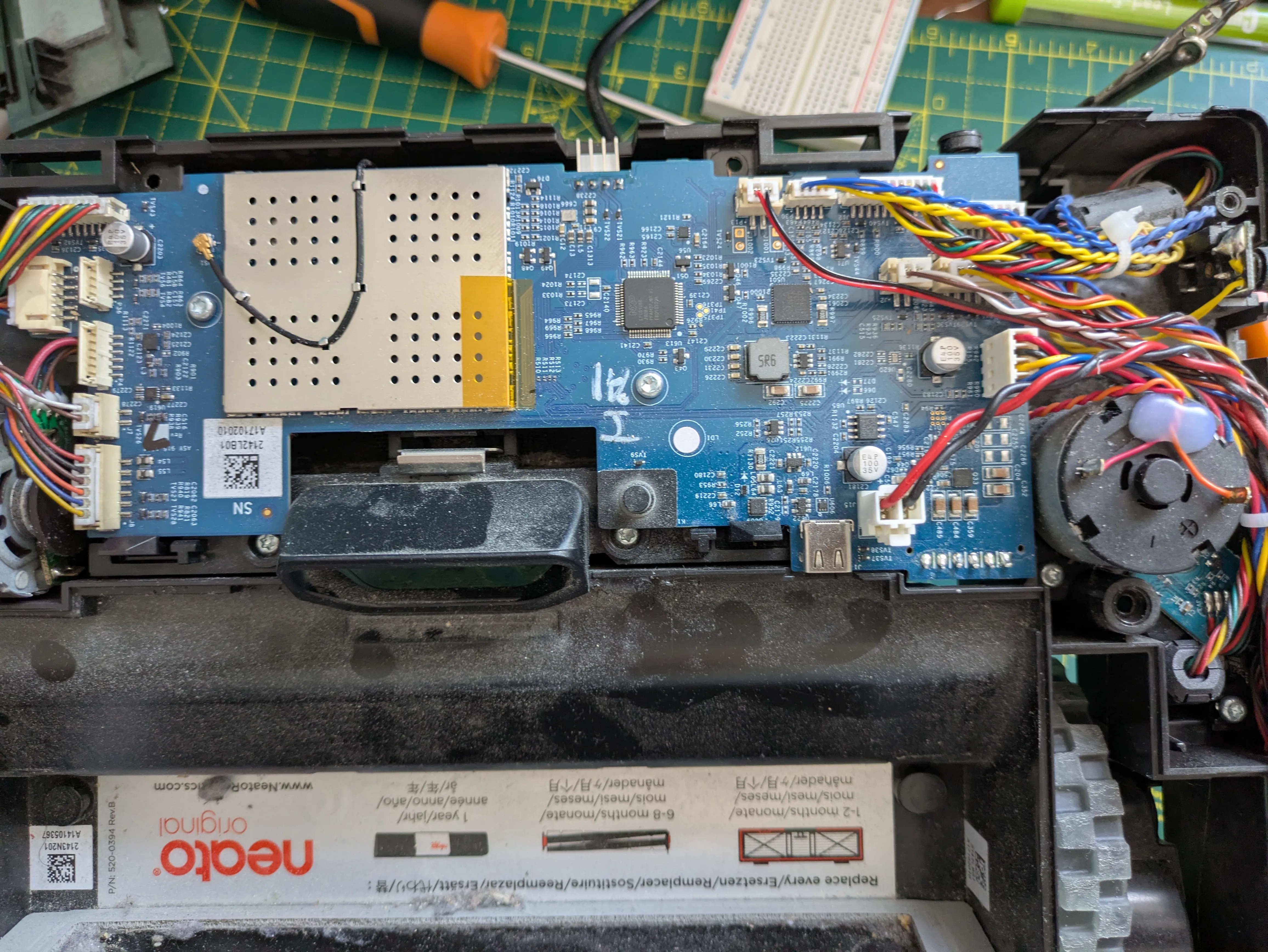
Teardown day. Screwdrivers out, phone camera ready, and a growing pile of little screws I’m absolutely going to lose.
I went in with a rule: photograph everything before I unplug it, and read every label I can find. When you’re going to throw away the brain and keep the body, the body’s part numbers are the documentation. Nobody’s shipping me a datasheet.
Here’s what’s inside.
The mainboard. Marked 520-0394 Rev.B, with a USB-C port silkscreened “SW Update” — a service port for factory firmware, not that it does me any good given the locked boot chain from last episode. The main chip is the NXP LPC51U68 I mentioned: Cortex-M0+, 256 KB flash. Confirmed with my own eyes now. This is the brain that’s getting binned.
The WiFi/Bluetooth module. Tucked under a perforated RF shield with a little U.FL antenna lead. This is the bit that used to phone home to the cloud that no longer exists. Discard.
The button board. A small separate PCB, actually branded neato, with test points TP1 through TP22, sitting under the power and reset buttons. Discard — I’ll wire my own buttons to the ESP32 if I even want physical buttons.
And then the part I was hoping for.
The LiDAR. It’s a Neato LDS 2.2 — silkscreen 290-1044 REV 4, copyright 2019. And this is the whole ballgame, because the Neato LDS is quite possibly the most reverse-engineered laser scanner in all of hobby robotics. The XV-11 generation of these has been decoded to death for over a decade. There’s existing driver code sitting in public repos (the ssloy and berndporr ones, among others). The single hardest part of building a mapping robot — a working laser scanner and the code to read it — I was worried I’d have to reverse-engineer from scratch. Instead it fell out of the case with a pedigree.
The interface, from the silkscreen and what’s documented for the family: 8N1 UART, 3.3 V, 115200 baud. Two connectors — J2 MAIN carries 5 V power in and the serial scan data out, and J3 MOTOR drives the spin motor (which you PWM in a closed loop off the reported RPM). There’s an LM393 comparator on the chip side, the classic design. I’ve noted the one thing I still have to confirm — whether the 2.2’s packet format exactly matches the documented XV-11 format or needs a tweak — but that’s a “verify with a logic analyzer” job, not a “hope this is possible” job.
The rest of the salvage:
- Battery — Li-ion, 14.4 V nominal, a 4S2P pack, 6200 mAh / 89 Wh. Real voltage swings 12 V empty to 16.8 V full. Six-pin JST connector — power plus what I think is a thermistor/sense line, pinout still to map.
- Drive wheel motors —
260-0016, 14.4 V, brushed DC. No current rating printed on them, which becomes a whole saga later. - Wheel encoders — labelled
LEGO WHEEL ENCODER ASY: 915-1055. The disc is solid, not slotted, which means it’s almost certainly magnetic (Hall), not optical. That’s good news — magnetic sensing shrugs off dust, and this is a vacuum cleaner. - Roller brush motor —
905-0460, 14.4 VDC, brushed. Also no current rating. - The blower. An EVERFLOW
F121225BU, and this one does print its numbers:DC14.4V 2.0AMP. That…BUsuffix matters, but I’ll save why for the motor episode.
One gotcha worth flagging so nobody fries anything: there’s a 19.5 V 1.5 A figure on the device plate. That is not the battery — that’s the dock charge input. The battery is 14.4 V. When I tap power for the new electronics, I tap the 14.4 V pack, not the plate number.
So the tally: I’m keeping the chassis, both wheel motors, the brush motor, the blower, the LiDAR, the battery, and the sensors. I’m binning the mainboard, the WiFi module, and the button board. The teardown’s essentially done, everything’s photographed, and the scary part — the LiDAR — turned out to be the friendly part.
Next: deciding, properly, what lives and what dies, and sketching the new nervous system that replaces the brain I just condemned.